

NDT for Dished Heads: What UT, MT and PT Actually Find

A dished head is usually ordered with an NDT requirement copied from the vessel specification, and that requirement is usually written for welds. A seamless head has almost none. What a head actually needs examined is something else: the wall left after forming, the surface left by forming, and the joints that attach it later. UT, MT and PT cover those three targets, and they do not substitute for one another.
Three targets, three methods
Section V of the ASME Code supplies the methods. Section VIII Division 1, EN 13445 or B31.3 supplies the acceptance criteria. Confusing the two is where most scope disputes start: Section V tells an inspector how to make the examination, not whether the result passes.
|
Method |
What it finds |
Material limit |
Where it applies on a head |
What it cannot do |
|
RT - Art. 2 |
Volumetric flaws in welds: porosity, slag, lack of fusion |
Any |
Seams inside a fabricated head, head-to-shell joint, nozzle welds |
Nothing on a seamless head; there is no weld to shoot |
|
UT of welds - Art. 4 |
Planar flaws: cracks, lack of fusion, sidewall lack of penetration |
Any |
Thick seams where RT is impractical or specified instead |
Needs access and coupling; curvature limits near the knuckle |
|
UT of thickness - Art. 5 |
Wall thickness, local thinning, remaining section |
Any |
Crown, knuckle, straight flange, after forming |
Does not characterise small internal flaws or surface cracks |
|
MT - Art. 7 |
Surface and near-surface cracks |
Ferromagnetic only: carbon, low-alloy, martensitic stainless |
Carbon steel heads after forming, weld toes, heat-affected zones |
No useful indication on austenitic stainless, nickel alloy, aluminium, titanium |
|
PT - Art. 6 |
Surface-breaking defects: cracks, laps, porosity open to the surface |
Any non-porous material |
Stainless and nickel-alloy heads, weld caps, pickled surfaces |
Only what reaches the surface; rough surfaces give false background |
|
VT - Art. 9 |
Form, fit-up, surface condition, weld profile |
Any |
Every head, before and after forming |
Sees nothing below the surface |
The table is deliberately blunt about MT. Magnetic particle examination needs a ferromagnetic path for the flux. Austenitic stainless has none, so a 304 or 316L head cannot be examined by MT, and a report that claims it was has described an examination that could not have produced a meaningful result.
Where each method lands on the head
|
Region |
What changes there |
Method that answers it |
|
Crown |
Little forming strain, but full membrane stress under pressure |
UT thickness, VT, surface examination of any seam |
|
Knuckle |
Highest forming strain and the thinnest wall on the part |
UT thickness on a grid, then PT or MT after forming |
|
Straight flange |
Weld preparation, dimensional fit to the shell |
VT, dimensions, UT thickness, weld NDT after attachment |
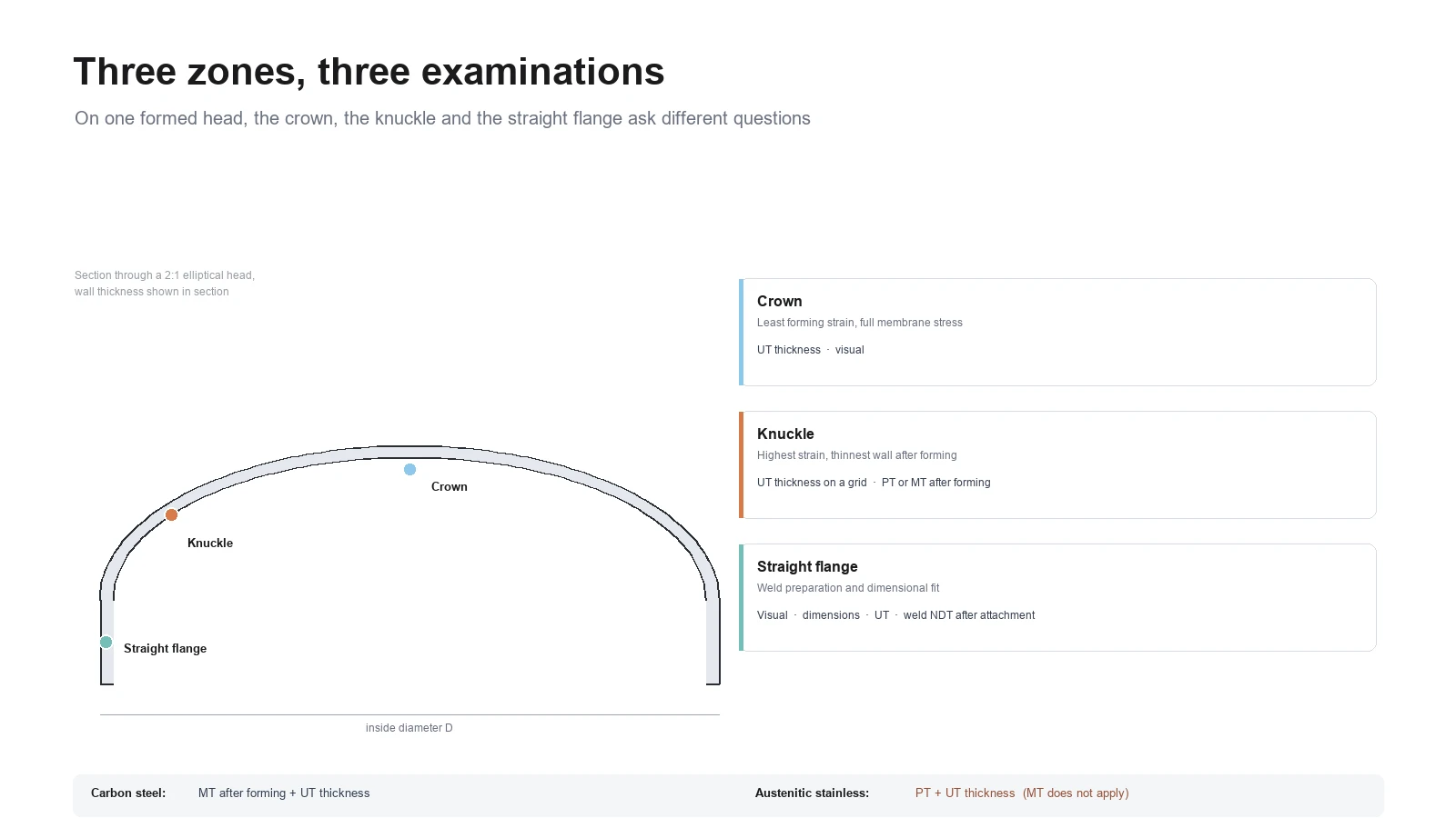
The point most specifications miss: a seamless head has no weld to radiograph
A seamless 2:1 elliptical head is pressed or spun from a single plate. There is no longitudinal seam to shoot, and no circumferential seam until the head is welded to a shell. When a purchase order says ten percent radiography and the head arrives seamless, the radiography applies to the head-to-shell joint and to the nozzle welds. It does not apply to the head.
That has two consequences, and both are practical.
The first is design. Under UW-12(d), a seamless head is credited with a joint efficiency of 1.00 only when its connecting weld has been spot examined to UW-11(a)(5)(b). Without that spot film, the efficiency falls to 0.85, and the head has to be thicker to carry the same pressure. The radiograph on the joint is not a paperwork step. It is part of the thickness calculation, and it is decided at the design stage, not at goods-in.
The second is the inspection plan. If the only NDT written into the order is radiography of welds, then nothing has been specified to check the wall after forming - and that is where the real risk sits, because the knuckle thins. A head can pass every weld film and still be below the minimum thickness at the transition.
Thickness is the examination a head actually needs
Cold spinning pulls the wall over the tightest radius at the knuckle. On a 2:1 elliptical head in SA516 Gr.70 formed from 20 mm plate, thinning of 8 to 12 percent at the knuckle is normal. Pressing is more uniform, typically 5 to 8 percent. Neither number is a defect. It becomes one when the finished wall drops below the UG-32 minimum, which UG-79 does not permit at any point on the head.
A single reading at the crown will not find that. The measurement plan has to place points at the crown, across the knuckle on several meridians, and on the straight flange, and record each location separately. A report that states one minimum figure for the whole head cannot tell a vessel inspector whether the thin point is at the knuckle, where it is expected, or somewhere it should not be.
A workable plan for a mid-size head: three points on the crown, four meridians across the knuckle with three points each, and four points on the straight flange. That is twenty-five readings, it takes minutes on a formed head, and it produces a map instead of a number.
The material decides the surface method, not the drawing
MT magnetises the part and looks for particles that gather where flux leaks out of the surface. That only happens in ferromagnetic material. Carbon steel and low-alloy steel heads take MT without difficulty, and so do martensitic stainless grades. Austenitic stainless - 304, 316L, 321 - does not, and neither do nickel alloys, aluminium or titanium. Specifying MT on a 304L head produces either no indication or a misleading one, and the signature on the report certifies nothing.
For those materials the method is PT. It relies on capillary action rather than magnetism, so it works on any non-porous surface. One caution is written into Section V Article 6: penetrant materials used on austenitic stainless, nickel alloys and titanium carry limits on sulfur and halogen content, because residue left in a crack or a lap can initiate stress corrosion later. A shop that buys the cheapest penetrant on the shelf can create the condition it was hired to detect.
Surface preparation decides the result as much as the method. PT on a freshly pickled or blasted surface that has not been cleaned and neutralised gives a fluorescent background that hides small indications. The surface has to be clean and dry, and the developer needs its dwell time.
When each examination happens
|
Stage |
Examination |
Why at that point |
|
After forming |
VT, dimensions, UT thickness at crown, knuckle and flange |
Thinning is final, and forming cracks are open and visible |
|
After heat treatment |
MT or PT on welds and heat-affected zones |
Heat treatment can open cracks that forming did not |
|
After welding to shell or nozzles |
RT or UT to the applicable plan; MT or PT at weld toes |
Joint examination belongs to the joint, not to the head |
|
Before hydrotest |
All reports reviewed and accepted |
The pressure test proves tightness and strength, not flaw detection |
What to read in the report package
The method standard and its edition, for example Section V Article 5 with ASTM E797 for thickness.
Coverage, stated as points or percentage, not as examined and accepted.
Locations that could not be read, and the reason. A missing row is worse than a low reading.
The acceptance criterion, quoted from the construction code rather than the NDT procedure.
Personnel qualification: SNT-TC-1A or ISO 9712 Level II, with the employer certification on file.
Write the scope into the order
An order that says NDT as per code leaves the scope to the shop. This wording closes the gaps that matter on a head:
Nondestructive examination: visual and dimensional examination of the formed head;
ultrasonic thickness measurement at the crown, knuckle (four meridians, three points
each) and straight flange, recorded by location, minimum acceptable thickness per
UG-32 after forming; surface examination of welds by PT for austenitic material and
MT for ferritic material, after final heat treatment; radiographic examination of the
head-to-shell joint in accordance with the applicable RT plan.
Dished heads and inspection at Dalian Dingjin
We form elliptical, torispherical and hemispherical heads in carbon steel and stainless steel, from two production bases and one R&D center in Dalian, and have supplied pressure vessel closures for more than 24 years. The plant holds a third-class pressure vessel manufacturing license and fabricates to ASME and other cited codes. Plate is checked for chemistry, mechanical properties and surface quality before it enters production, each formed head is measured after forming with thickness recorded by location, and since 2014 we have shipped an average of more than 1,000 tons of dish heads a year.
FAQ
Q: Does a seamless head need NDT at all?
A: Yes, but not the same NDT that a welded vessel needs. There is no weld on the head to radiograph. What needs checking is the wall after forming and the surface condition after forming, and radiography applies to the joints once the head is attached to the shell or to nozzles.
Q: Why can a 304 head not be examined by magnetic particle testing?
A: MT depends on a ferromagnetic material carrying magnetic flux. Austenitic stainless is not ferromagnetic, so no meaningful flux leakage forms at a defect. For these grades the surface method is liquid penetrant, and the penetrant has to meet the sulfur and halogen limits in Section V Article 6.
Q: Where should thickness be measured on a formed head?
A: At the crown, across the knuckle on several meridians, and on the straight flange, recorded as separate locations. The knuckle is where forming strain is highest and where the wall is normally thinnest, so a single crown reading proves nothing about the part.
Q: Should NDT be completed before or after the hydrotest?
A: Before. Examination is normally completed and accepted before the pressure test. The hydrotest verifies tightness and strength under pressure; it does not detect lack of fusion, and it does not measure wall thickness.
Q: Can ultrasonic testing replace radiography on welds?
A: Sometimes, and only where the construction code permits it. UT is stronger on planar flaws and on thickness, while RT leaves a volumetric record that is easier to review later. The substitution is a code decision, so confirm it with the inspector before the order is placed, not after the welds are made.